
BASIC INFO
P+F KCD2-STC-Ex1.2O.ES isolated barrier SMART Transmitter Power Supply 24 V DC supply Analog input
Features
• 1-channel isolated barrier
• 24 V DC supply (Power Rail)
• Input for 2-wire SMART transmitters and current sources
• Signal splitter (1 input and 2 outputs)
• Dual output 0/4 mA ... 20 mA or 0/1 V ... 5 V
• Terminal blocks with test sockets
• Up to SIL 3 acc. to IEC 61508
Function
This isolated barrier is used for intrinsic safety applications.
The device supplies 2-wire transmitters in the hazardous area,
and can also be used with current sources.
It transfers the analog input signal to the safe area as two
isolated output signals.
Bi-directional communication is supported for
SMART transmitters that use current modulation to transmit
data and voltage modulation to receive data.
The output is selected as a current source, current sink, or
voltage source via switches.
Test sockets for the connection of HART communicators are
integrated into the terminals of the device.
Application
The device supports the following SMART protocols:
• HART
• BRAIN
General specifications
Signal type Analog input
Functional safety related parameters
Safety Integrity Level (SIL) SIL 3
Supply
Connection Power Rail or terminals 9+, 10-
Rated voltage Ur 18 ... 30 V DC
Ripple within the supply tolerance
Power dissipation approx. 1.4 W at 20 mA transfer current, 250 ohm in both outputs
Power consumption 2 W
Input
Connection side field side
Connection terminals 1+, 2- (sink); 3+, 4- (source)
Input signal 0/4 ... 20 mA
Voltage drop terminals 3, 4: ≤ 6.1 V at 20 mA
Short-circuit current terminals 1+, 2-: 25 mA
Input resistance terminals 1+, 2-: ≤ 500 ohm
(250 ohm load)
Available voltage terminals 1+, 2-: ≥ 16 V at 20 mA , ≥ 18.5 V at 4 mA
Output
Connection side control side
Connection source: terminals 5-, 6+; 7-, 8+
sink: terminals 5+, 6-, 7+, 8-
Load channel 1: 0 ... 500 ohm (20 mA)/> 1 Mohm (5 V)
channel 2: 0 ... 500 ohm (20 mA)/> 1 Mohm (5 V)
Output signal 0/4 ... 20 mA or 0/1 ... 5 V
Ripple ≤ 50 µA rms
Transfer characteristics
Deviation Iout < 20 µA (0.1 %); Vout < 10 mV (0.2 %) incl. calibration, linearity, hysteresis and fluctuation of supply voltage,
at 20 °C (68 °F), 0/4 ... 20 mA, 0/1 ... 5 V
Influence of ambient temperature current output: 0.25 µA/K
voltage output: 80 µV/K
Frequency range field side into the control side: bandwidth with 0.5 Vpp signal 0 ... 6 kHz (-3 dB)
control side into the field side: bandwidth with 0.5 Vpp signal 0.3 ... 6 kHz (-3 dB)
Settling time 6 ms
Rise time/fall time 2 ms
Galvanic isolation
Output/power supply functional insulation, rated insulation voltage 50 V AC
Output/Output functional insulation, rated insulation voltage 50 V AC
Indicators/settings
Display elements LED
Control elements DIP-switch
Configuration via DIP switches
Labeling space for labeling at the front
Directive conformity
Electromagnetic compatibility
Directive 2014/30/EU EN 61326-1:2013 (industrial locations)
Conformity
Electromagnetic compatibility NE 21:2012
EN 61326-3-2:2008
Degree of protection IEC 60529:2001
Protection against electrical shock UL 61010-1:2012
Ambient conditions
Ambient temperature -20 ... 60 °C (-4 ... 140 °F)
Mechanical specifications
Degree of protection IP20
Connection screw terminals
Mass approx. 100 g
Dimensions 12.5 x 114 x 122 mm (0.5 x 4.5 x 4.8 inch) , housing type A2
Mounting on 35 mm DIN mounting rail acc. to EN 60715:2001
Data for application in connection
with hazardous areas
EU-Type Examination Certificate BASEEFA 13 ATEX 0077 X
Marking ¬ II (1)G [Ex ia Ga] IIC
¬ II (1)D [Ex ia Da] IIIC
¬ I (M1) [Ex ia Ma] I
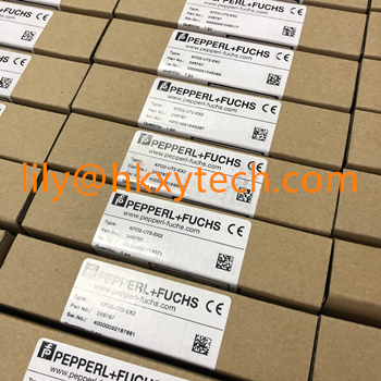
Order number:
KCD2-STC-Ex1
KCD2-STC-Ex1.ES
KFD2-CRG2-Ex1.D
KFD2-HLC-Ex1.D
KFD2-HLC-Ex1.D.2W
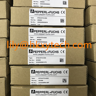
KFD2-STC4-Ex1
KFD2-STC4-Ex1.2O
KFD2-STC4-Ex1.2O.H
KFD2-STC4-Ex1.H
KFD2-STC4-Ex2
KFU8-CRG2-Ex1.D
KCD2-STC-Ex1.2O
KCD2-STC-Ex1.2O.ES
KCD2-STC-Ex1.ES.SP
KCD2-STC-Ex1.SP
KFD2-STC3-Ex1
KFD2-STC4-Ex1-Y1
KFD2-STC4-Ex1.2O-Y1
KFD2-STC4-Ex1.ES
KFD2-STC4-Ex2-Y1
KFD2-STC5-Ex1
KFD2-STC5-Ex1.2O
KFD2-STC5-Ex1.2O.H
KFD2-STC5-Ex1.H
KFD2-STC5-Ex2
KFD2-STC5-Ex2
KFD2-STC5-Ex2
KFD2-STV4-Ex1.2O-1
KFD2-STV4-Ex2-1
KFD2-STV4-Ex2-2
KFD2-STV5-Ex1-1
KCD2-STC-Ex1.2O.DE
KFD2-HLC-Ex1.D.4S
KFD2-STV4-Ex1.2O-2
KCD2-STC-Ex1.HC
KCD2-STC-Ex1.HC.SP
KFD2-STC4-Ex1
KFD2-STC4-Ex1-Y1
KFD2-STC4-Ex1.2O
KFD2-STC4-Ex1.2O-Y1
KFD2-STC4-Ex1.2O.H
KFD2-STC4-Ex1.H
KFD2-STV4-Ex1-1
KFD2-STV4-Ex1-2
KFD2-STV4-Ex1.2O-1
KFD2-STV4-Ex2-1
KFD2-STV4-Ex2-2
KFD2-STV4-Ex1.2O-2
KFD2-STC3-Ex1
KCD2-STC-Ex1-Y1
-----------------------------------
Lily
HONGKONG XIEYUAN TECH CO., LIMITED
T: 86-027-85581877 F: 86-027-85309780
Mail:lily@whxyauto.com
Ad: 7-A16,Caishen Commercial Plaza,Hankou Railway Station,Wuhan, Hubei, China
Web: www.hkxytech.com
Pre:P+F KCD2-STC-Ex1.2O isolated barrier Transmitter Power Suppl
Next:P+F KCD2-STC-Ex1.ES.SP isolated barrier Transmitter Power Su